Tutorial - Manual parametrizing your first DXF file
Let’s learn by example.
In this tutorial, we will learn how to parametrize a DXF file.
We’ll assume you have QSketchMetric installed already as well as QCAD Professional
First download the tutorial_param.dxf file from the QSketchMetric repository. It is an example of a DXF file that we will parametrize in this tutorial.
To do so, open it and click Ctrl+S to save it to your computer.
As a convention, we’ll assume you saved it in a file called tutorial_param.dxf.
First, let’s open the file in QCAD Professional. (File -> Open)
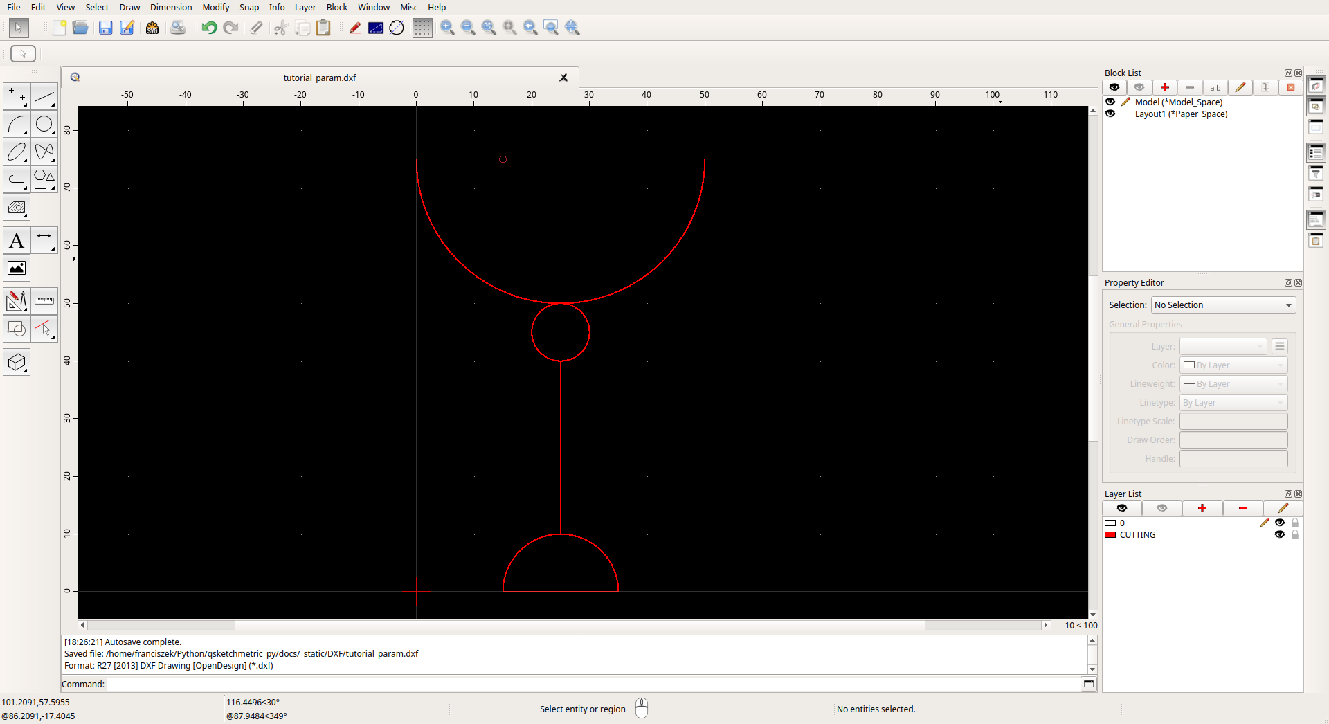
As you can see, it is a simple drawing of a chalice. With every entity placed on the CUTTING layer.
We would like to parametrize it depending on the given size of the
chalice. We will call chalice height variable: h.
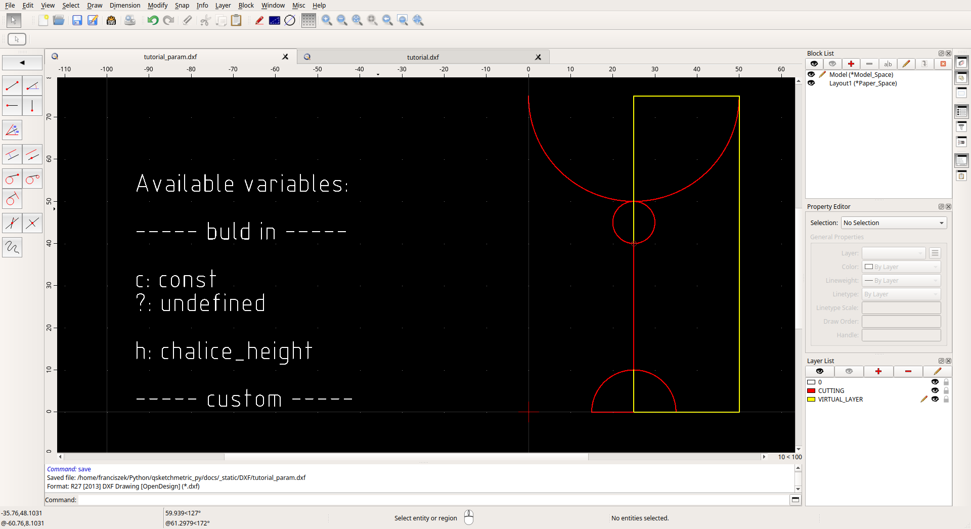
Let’s start by adding a MTEXT. entity to the drawing and placing it at the left of the chalice. (Draw -> Text) To the text input field add the following text:
Available variables:

----- build in -----

c: const
?: undefined

h: chalice_height

----- custom -----
- Where:
‘—– build in —–’: are the built-in variables it servers as a documentation for the user. We added
hvariable to know what is the variable name for the chalice height.‘—– custom —–’: are the helpers variables that we will add later.

The next step will be adding a new layer called VIRTUAL_LAYER (Layer -> Add Layer) and drawing LINE entities on it. (Draw -> Line -> Line from 2 Points) With those lines join all the points of a chalice to each other to form a cohesive graph.
CIRCLE - by their center point
LINES - by at lest one of their end points
ARC - by their center point
After you are done, you should have something like this:
We are nearly finished. The last step is to add parameters to the drawing. But first, let’s make our job easier by defining a few helper variables. In the — custom — section of the MTEXT entity add the following variables:
----- custom -----

chalice_foot_radius: h * 1/5
chalice_bowl_radius: h * 2/5
chalice_ornament_radius: h * 1/10
Chalice arc-bowl, arc-foot and circle-ornament radius’s are defined as a fraction of the chalice height. This way, if we change the chalice height, the radius’s will change accordingly.
We did not define the chalice leg length because it will be calculated automatically by the renderer.
After adding the variables, everything should look like this:

Now we can add parameters to the drawing. To do so select the entities one by one and scroll down the
Property Editor to the Custom section. Click on the red plus button and add the parameter.
Namemust be: c.
Valuecontains the expression describing the entity. According to this table below
Value
Description
c(constant) Entity length will not change
?(undefined) Entity length will be calculated by the renderer. Only if there is other path to the both end points of the line!
c/h*2(math expression) Entity length will be calculated from the math expression
Attention
Remember that our goal is to parametrize the drawing depending on the chalice height.
To parametrize the drawing depending on the chalice height, the Value for the virtual line on the right side
of the chalice must be h and for the chalice leg line must be ?. By doing so, we are telling the renderer
to calculate the length of the chalice leg line from two end points of the line.
Visual representation of the parametrized drawing:

Warning
It is just a visual representation of the parametrized drawing. It does not represent the actual look of the parametrized drawing. Actual look of the parametrized drawing doesn’t change after the parametrization!
Now we can save the parametrized DXF file (File -> Save) and render it. Finished file should be simular to tutorial.dxf file, that you can download from the QSketchMetric repository.
Lastly, we check if the parametrization is correct by validating it. To do so, follow the Validation your first DXF file tutorial.
Congratulation you created your first parametric DXF file!