Manual parametrization
Supported DXF entities
QSketchMetric explicit supports the following DXF entities:
LINE, CIRCLE, ARC, POINT, INSERT entities. Other entities such as
LWPOLYLINE, POLYLINE, SPLINE, ELLIPSE, MTEXT, TEXT etc. can
be also parametrized, using the INSERT entity.
What is needed?
QCAD Professional is a commercial software, but it offers a free trial version. It is needed to embed the parameters into the DXF file. Community version of QCAD does not support this feature.
A DXF file to parametrize.
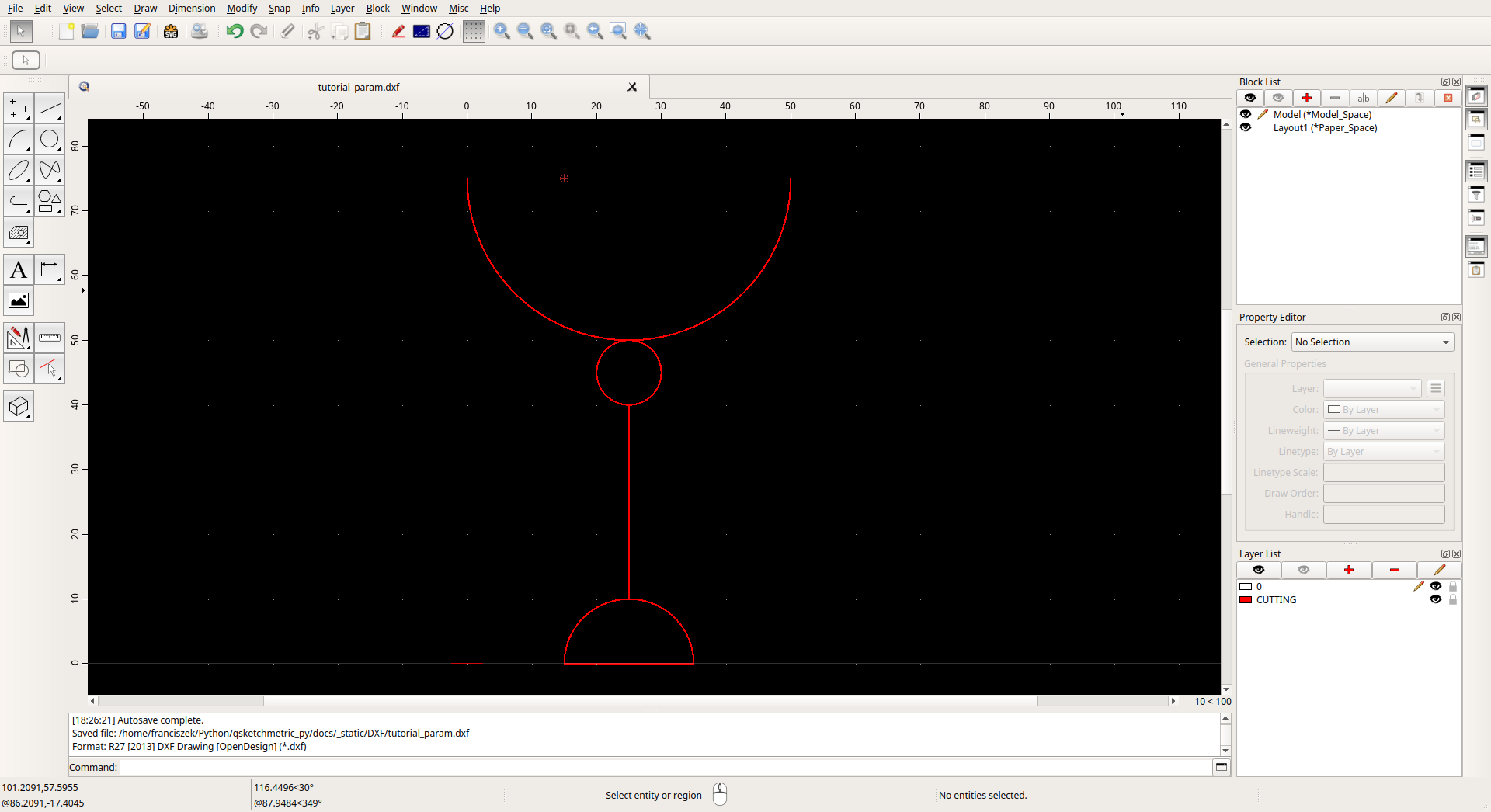
QCAD Professional with DXF file to parametrize opened
Manual parametrization
Open the DXF file in QCAD Professional. (File -> Open)
Add new layer called VIRTUAL_LAYER (Layer -> Add Layer)
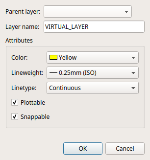
QCAD Professional layer adding window
Add MTEXT entity containing names of the variables passed to the renderer and variables added during parametrization. It can be placed anywhere. See MTEXT to get more information about the format of the entity. (Draw -> Text)
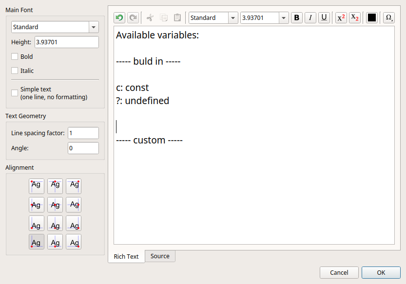
QCAD Professional with MTEXT dialog window opened
- Connect entities. Entities must be connected to each other.
CIRCLES - by their center point
LINES - by at lest one of their end points
ARCS - by their center point
POINTS - by their center point
INSERTS - by their insertion point
To achieve this add LINE entities (Draw -> Line) on to the VIRTUAL_LAYER. Those lines will connect the entities together and form one coherent graph. They won’t be rendered in the final DXF file.
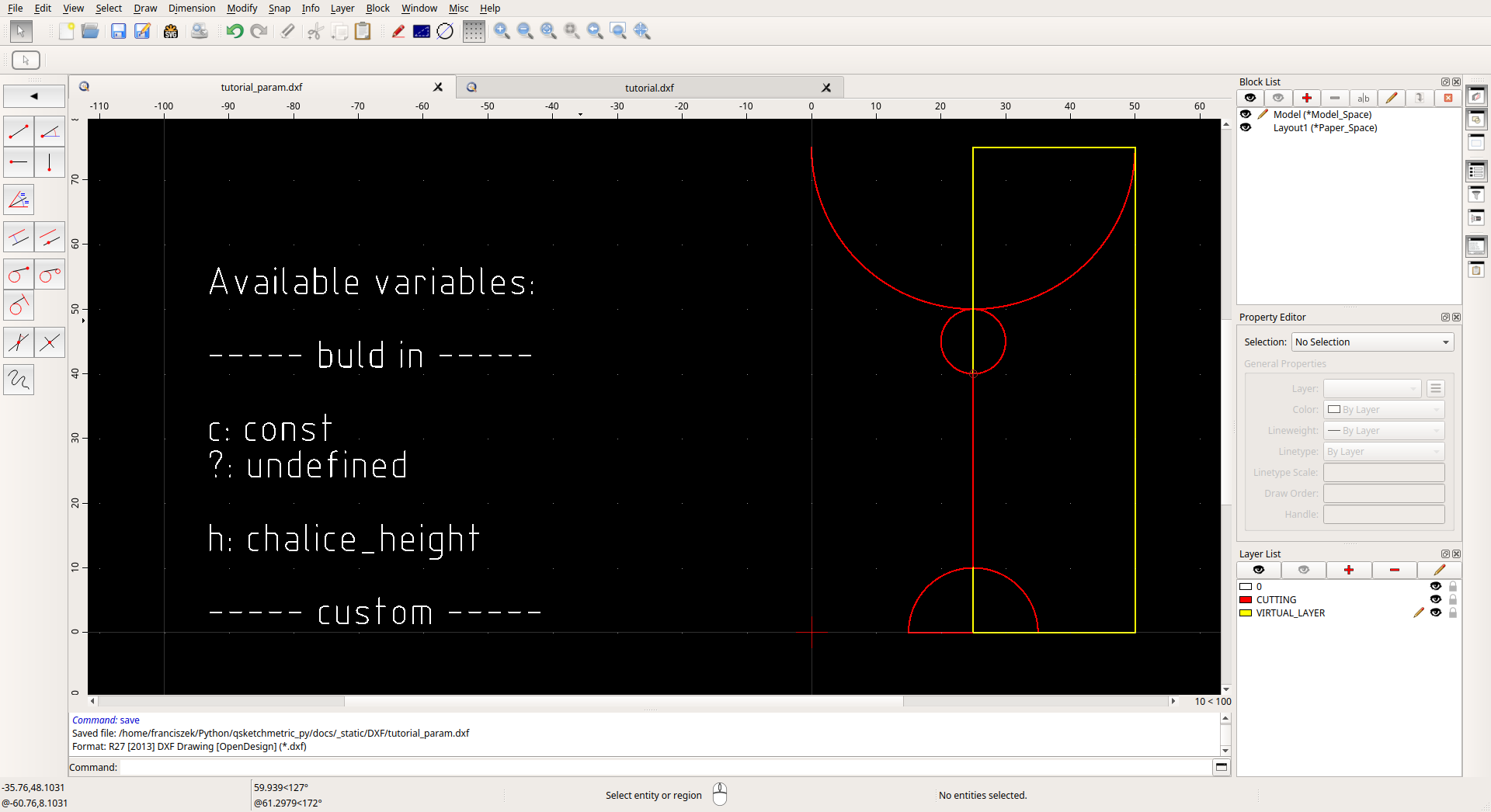
DXF drawing connected with lines
Final step is to add parameters to the entities. To do so select the entity and scroll down the
Property Editorto theCustomsection. Click on the red plus button and add the parameter.LINE,CIRCLEandARCNamemust be: c.Valuecontains the expression describing the entity. According to the table below.
Variables from the MTEXT entity can be used, as well as math expressions provided by this list.
There is an option to add optional
linevariable. This variables states the custom line style of the entity.Valueshould be in a format of ezdxf complex line pattern format. See ezdxf documentation for more information about the format.Valueexample: A,2,-1,[“BOWL”,STANDARD,S=.5,U=0.0,X=-0.1,Y=-.05],-2.5
INSERTNamemust be: c.Valuecontains the expression describing width and height of the entity split by a @ sign. In the format:width@height. Both width and height are math expressions (see above) where ? is only allowed for the one of the dimensions. For example: c*3@? or ?@200*sqrt(20). For the ? dimension the renderer will calculate the value to fit the aspect ratio of the entity.
Note
Entities on VIRTUAL_LAYER contained in
INSERTentity will not be rendered but they will be taken into account while calculating the width and height of theINSERTentity. This is useful to make calculations easier.For example: To parametrize a part of the ellipse, full ellipse on the VIRTUAL_LAYER can be drawn on top. This way by parametrizing the full ellipse the part will be rendered according to the full ellipse size. In many scenarios it is easier to parametrize.
LWPOLILINE,POLYLINE,SPLINE,ELLIPSE,MTEXTetc.Those entities must be packed into
INSERTentity and parametrized as described above.
POINTNamemust be: name.Valuecontains the name of the variable. This variable will be returned by theqsketchmetric.renderer.Renderer.render()in a dictionary.
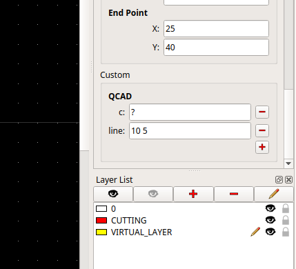
LINE entity with parameters
Validate the file. This can be done by using the QSketchMetric Validator. See Validating a parameterized DXF file for more information.